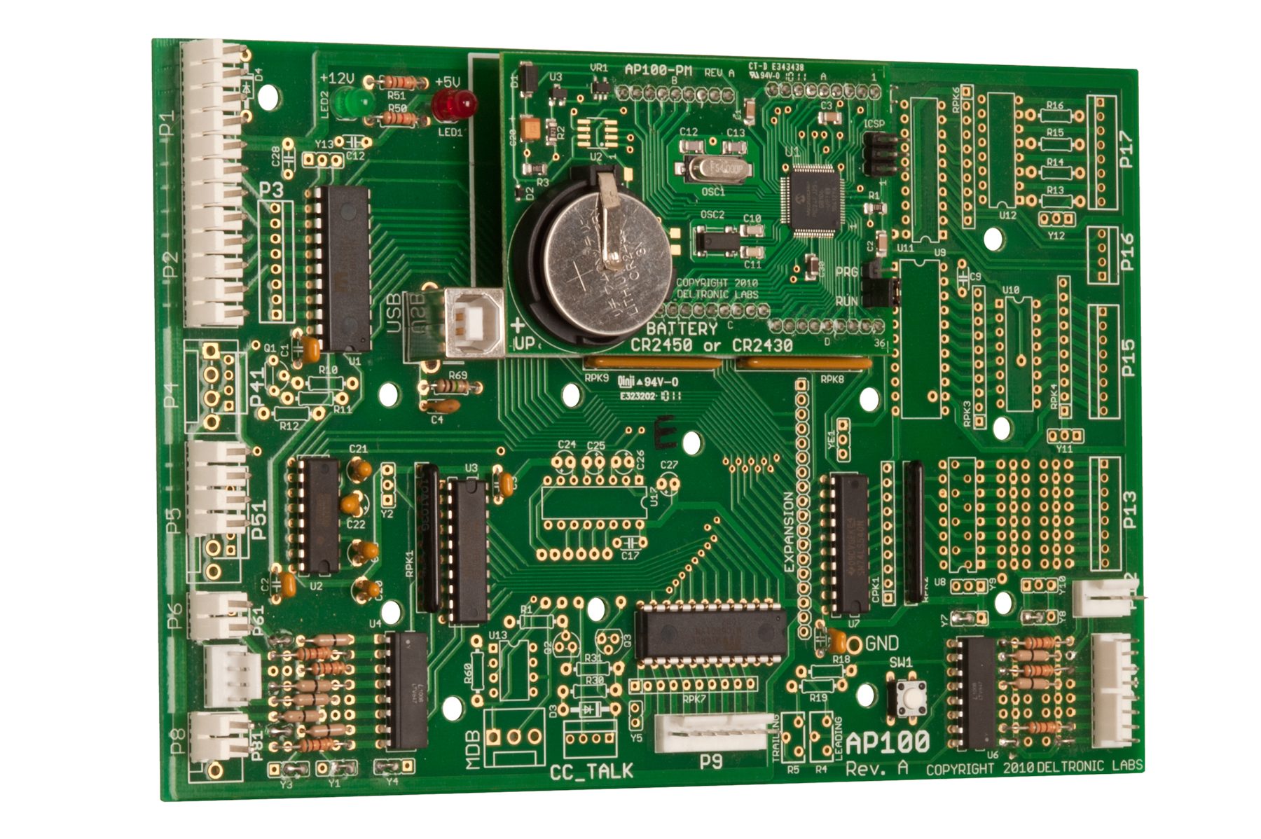
AP-100 BOARD
The AP-100 board is a flexible main logic board. It can accommodate many different applications by changing the firmware and build configuration. The main processor is a Microchip PIC24FJ256GB106 microcontroller on a daughter board that also includes a battery backup for the real-time clock. Sample firmware, custom bootloader, and custom programming (USA based) are available.
- Time-tested and proven control board
- USB HID interface
- 4 COM ports
- 24 bits of buffered output
- 16 bits of opto-isolated input
- Expansion header for additional IO and I2C
- Real-time clock with battery backup
- Power-loss detector
- Dimensions: 7.6 x 5.0 inches
- Power: + 5 VDC, (optional +12 VDC for IO)
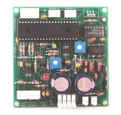
SOUNDER
- Add custom sound effects and music to games and attractions—any 22.05 Khz WAV file will work!
- Dual control inputs and dual output channels let one Sounder do the work of two sound boards
- Comes with software to easily download sounds and control details from PC to board
- Ideal replacement for older, more expensive sound boards
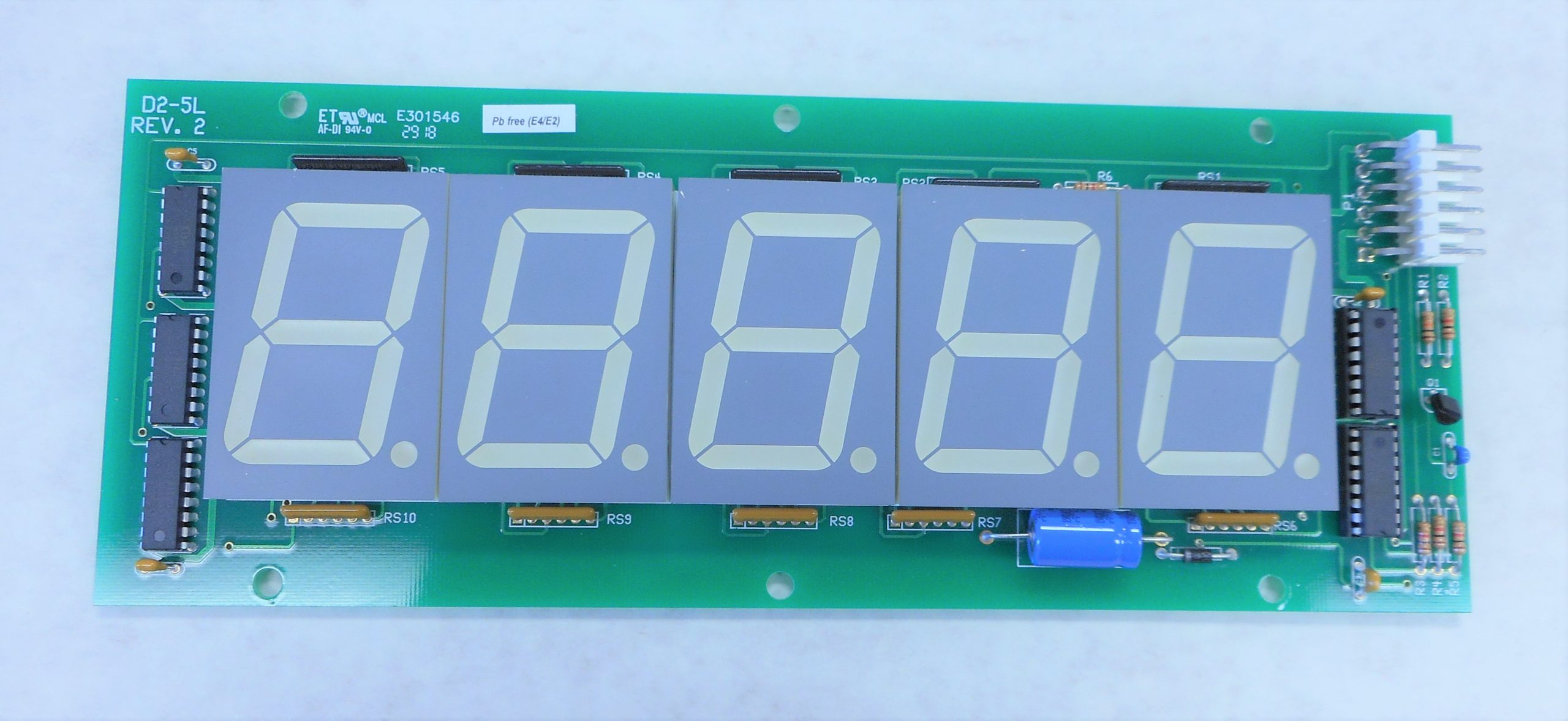
D2-5L
The display uses a three wire synchronous serial interface: Data, Clock, and Strobe. Data is transferred to a buffer on the rising edge of the clock. Data in the buffer is latched to the display on the rising edge of the Strobe. Each segment is individually controlled by a single bit.
- Five Digit, 7 Segment, Red LED Display
- Dimensions: 9.6 x 3.655 inches
- Digit size: 1.75 inches tall
- Display area: 7.6 x 2.2 inches
- Power +12 VDC
- Input Connector: ITW Pancon MPSS156-6-C
- Data
- Signal Ground
- Strobe
- Clock
- +12 V Power
- Power Ground
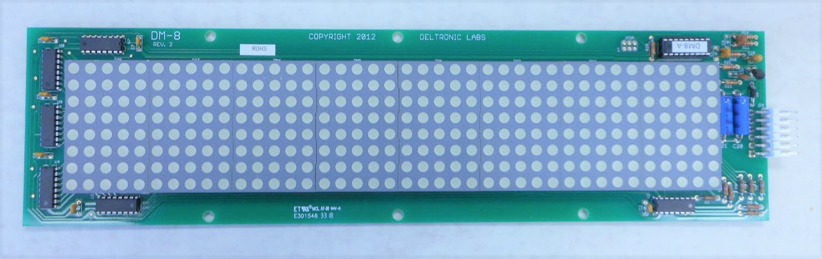
DM8
The display uses a synchronous serial interface. Data transfer is LSB first. Data is read on the rising edge of the clock. Communications is reset to the idle state after 96 ms without a clock transition. Most communications is done in packets. Packets are framed with ‘start’ and ‘end’ bytes. Packet data is ASCII. Packets too large to fit the display are automatically scrolled. Alternatively, a long message can be broken into non-scrolling pages by embedding page break control characters. Each page will automatically display in sequence. Start Blink and Stop Blink are sent stand-alone (no packet framing characters).
- 40 x 8 Dot Matrix Red LED Display
- Dimensions: 13.9 x 3.645 inches
- Display area: 12 x 2.4 inches
- Power +12 VDC
- Input Connector: ITW Pancon MPSS156-6-C
- 0x01 = start of data packet
- 0x02 = end of data packet
- 0x03 = end of data packet, display centered
- 0x04 = start blink
- 0x05 = stop blink
- 0x06 = use slow scrolling
- 0x07 = use fast scrolling
- 0x08 = page break
- Data
- Signal Ground
- Strobe
- Clock
- +12 V Power
- Power Ground